A door handle was required that met two criteria. First, it needs to work across two faces of the dodecahedron at a 116° angle. Second, it must be able to pull and hold the door shut tightly in an effort to minimize water entry. The following mechanism was designed. The bearing is three parts: a threaded tube, a stop, and a nut. The shaft and a stop make up the remainder of the moving parts. The handle, and latching mechanism are discussed further below.
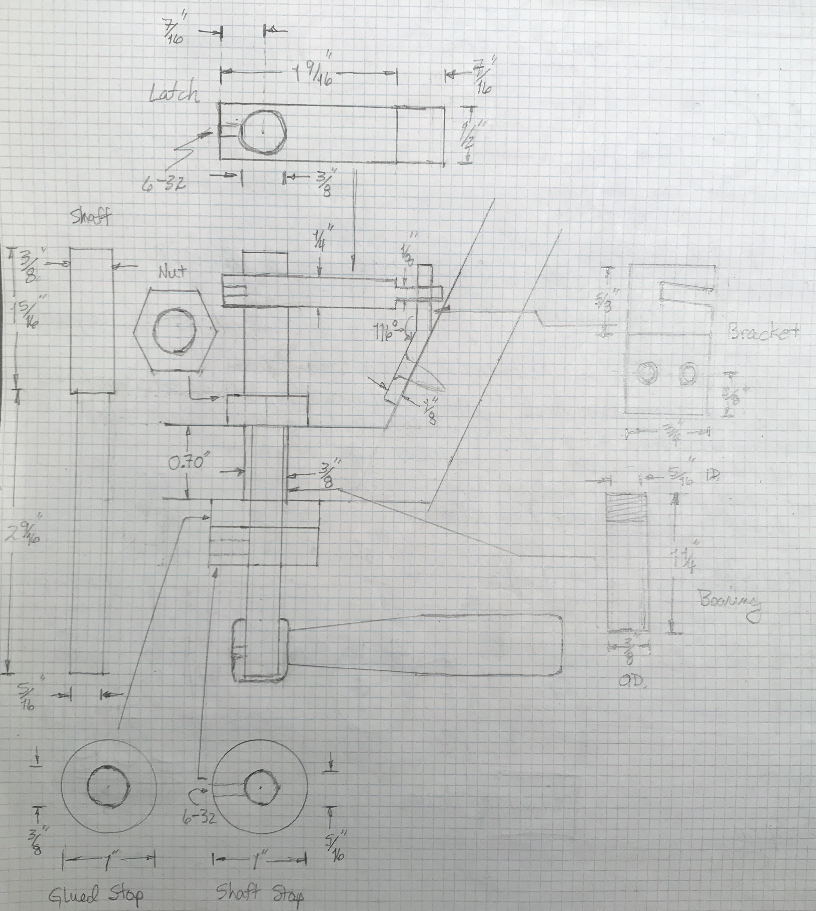
Not shown in the plan above is a critical dimension: the distance from the back edge of the door to the center of the hole for the bearing. This distance should be 1 1/8". (This is 1 9/16" from the front edge.)
A 3/8" X 1 1/4" length of brass tubing was reamed 3/16" and threaded 3/8-24 with a die, while a short length of steel was inside the tubing. The threads were cut to about 1/4" length. The ends were lightly chamfered inside and out. A 5/32" length of 1" brass hex was faced and drilled up to an O drill. The hole was then chamfered and threaded, 3/8-24, with a tap. A scrap of 1" X 1/4" round brass stock was faced, drilled, and reamed (5/16"). This stop was glued with Loctite to the unthreaded end of the tube. The thickness of the Baltic birch plywood used in the dodecahedron is 0.70". Consequently, with the current dimensions the stops on this bearing will fit tightly against both faces of the door.
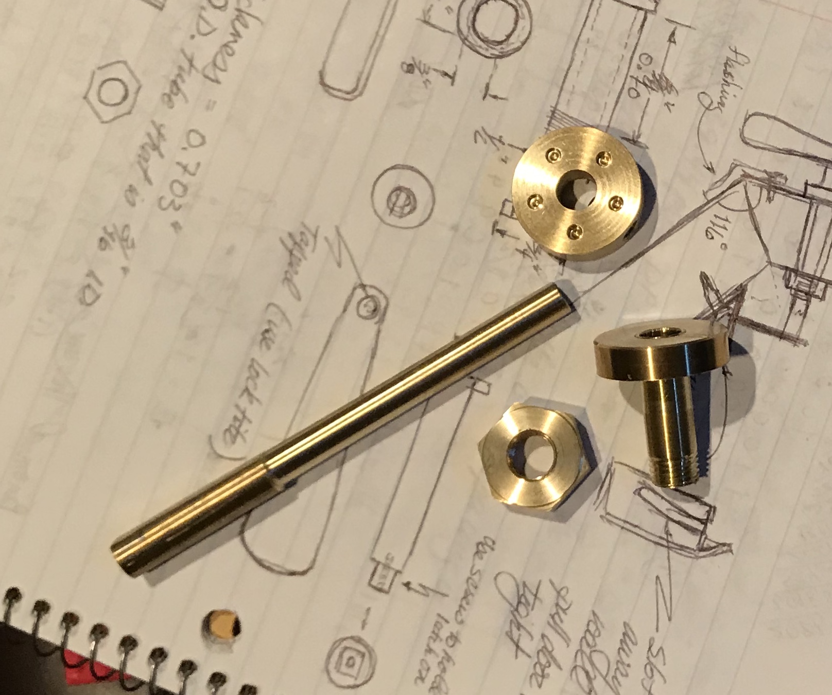
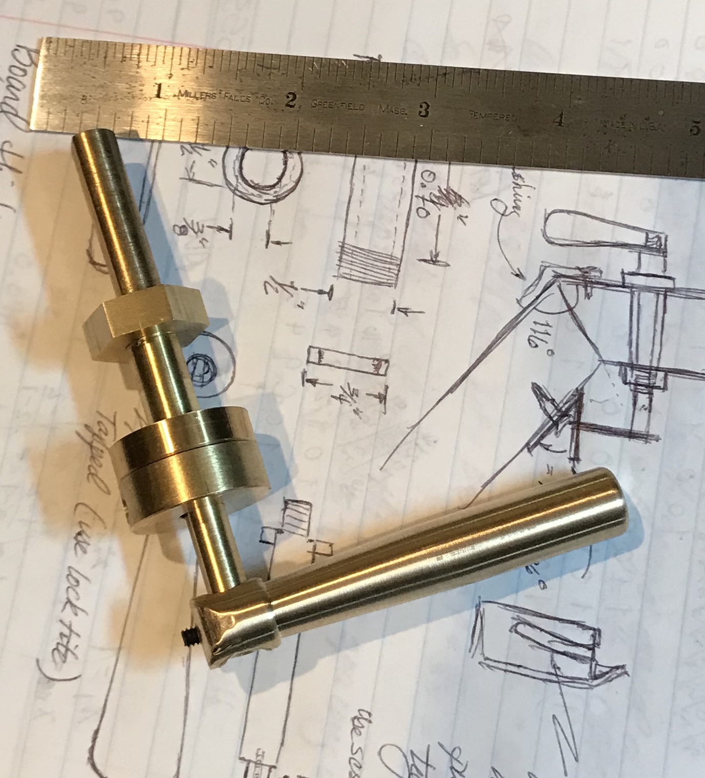
The shaft was made from a 4" X 3/8" scrap of brass round that had a flat cut the length of the piece. This brass stock was reduced to 3/16" diameter for a length of about 3" after drilling the end for a tailstock center. The unreduced end serves as a stop for the shaft on the inside of the door (against the nut). The outside stop was made from a scrap of 5/16" X 1" brass round. Both sides were faced and the hole in the center was opened and reamed to 3/16". This part was then cross drilled with a #21 drill and tapped 10-32. A 10-32 set screw was inserted to hold tight against the flat on the shaft.
Should a non-ferrous set screw be used here to avoid rusting?
The length of the shaft outside the door was about 1 1/2", so the gap between a handle afixed to the end of the shaft and the door face should leave sufficient room to easily grasp the handle. The handle was made from 3" X 1/2" brass round stock. It was cross drilled 1/4" from one faced end to 1/4" diameter for the rotary table. After clamping it to the rotary table supported by some waste material the drilled end was rounded until about a 1/8" flat was left on the end. The drilled end was held in the lathe and the head was angled to about 2.5°. The taper was cut on the shaft to a length of about 1.5" and a depth of 0.10" at the drilled end. The free end was rounded with a file and the entire handle was then filed and sanded to a matte finish. The hole for the shaft was then opened up by successively drilling with 9/32" and 5/16" drills. The shaft attaching end was then drilled with a #36 drill and tapped for a 6-32 set screw. The following picture shows the handle attached to the shaft.
The latch was made from a 2" length of 5/8" X 3/16" stock as opposed to the 1/2" X 1/4" stock shown in the plan. The material was squared up in the mill and one end was reduced in thickness by 0.060" for 7/16". This was done in 0.020" increments with a 3/8" end mill. This left a thickness of 0.124". The part was deburred, corners chamfered and sanded. A 3/8" hole 7/16" from the other end was made by drilling up to a U drill and then reaming. A hole was then drilled into the end of the part with a #36 drill and threaded 6-32 for a set screw.
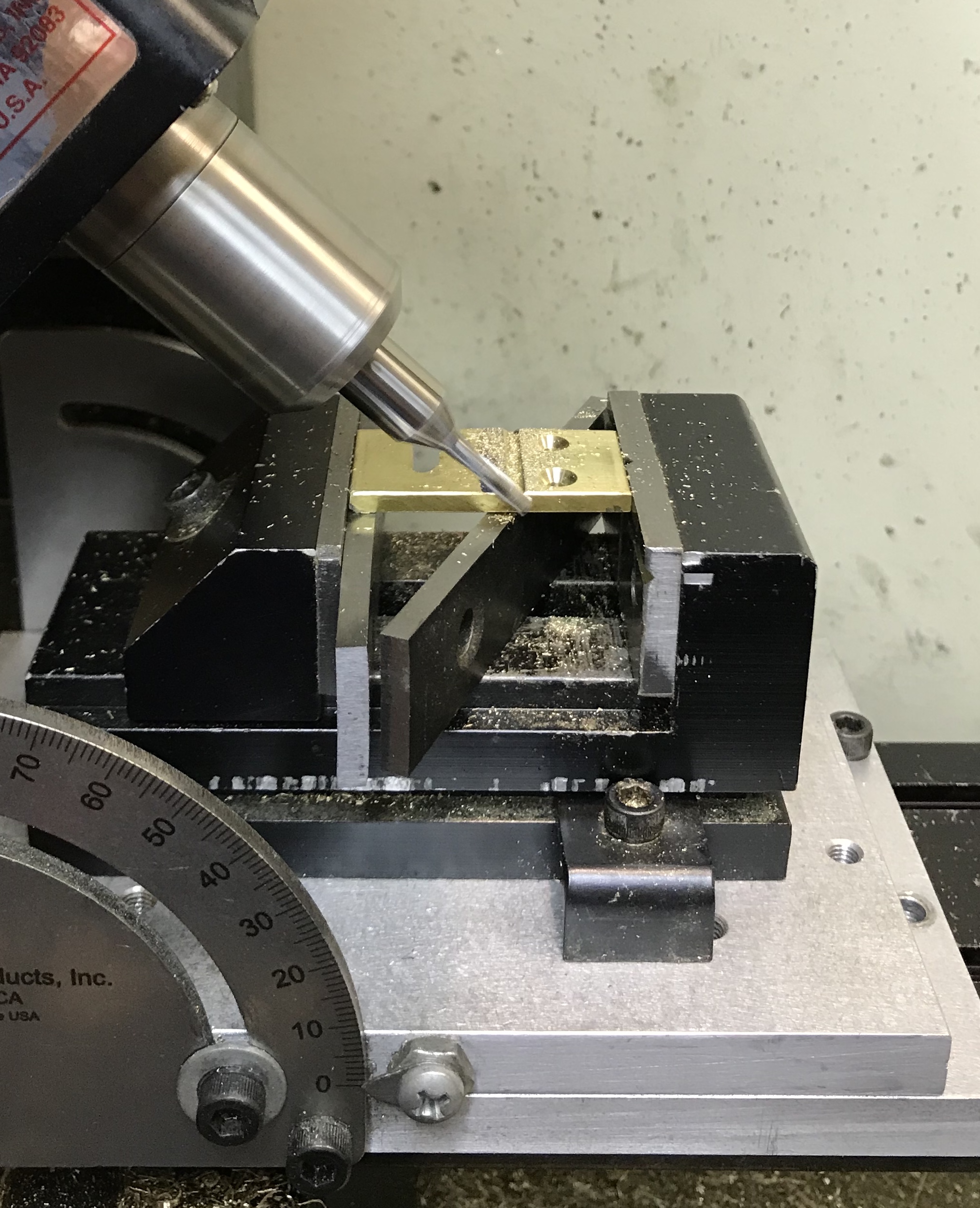
Found a scrap of 1/8" brass and cut it down to a 3/4" X 1 1/2" piece. Cleaned up the cut side with an end mill, chamfered corners and sanded. Marked out the positions for the two mounting holes; 3/8" from the bottom end and 3/16" in from each side. The holes were drilled with a #35 drill for a diameter of 0.110. (The wood screws selected are 0.107".) The holes were then countersunk sufficiently so the screws would lie flush with the surface. The slot was cut next. The straight edge of the slot was laid out 5/16" from the end of the part. The slot was cut in 0.010" passes to a length of 1/2". When the slot was cut through the vise was set at a 5° angle and the side closest to the screw holes was cut until the cut went the full 1/2" length of the slot. In order to bend this part a vee groove was cut. This was laid out 5/8" from the screw hole end. The head of the mill was rotated 45° and the vise was mounted on the angle plate (laid flat) to get the part high enough to cut with the tilted 1/8" end mill. The slot was cut 0.045" deep. Milling this slot is shown in the following photograph.
A few thoughts are in order prior to locating the bracket and assembling. The door should be drilled first. Next, the door should be hung on the living hinge. At this point the bracket can be located and attached. The latch can be adjusted in both length and shaft location to best fit the bracket. A further thought on the bracket design is that the opening for the latch should probably be widened at the top to provide some extra room for error and any changes due to temperature extremes.
The bracket was bent this morning. It was placed in the vise with the groove about 1/4" above the top of the jaws. The brass bracket was heated with a torch for about two minutes. (One minute was insufficient.) Pliers were used to bend the bracket. The protractor was used by sighting down the bracket and aligning it with the vertical part of the bracket. This seemed to get the bracket bent to within a degree or two. The bend is not as sharp as I expected. I guess the vee needed to be placed just above the top of the vise. The bracket was sanded to restore the finish.